

Keeping track of your basic vital statistics used to involve a trip to the doctor’s office where you would be subjected to expensive equipment that you couldn’t hope to understand. But now, with the rise of modular and kit electronics, you can build some of those devices right on your desk using a microcontroller like Arduino or Raspberry Pi Pico. With the return of winter and the rise of respiratory illness, it might be beneficial to have an easy-to-reach pulse oximeter. Granted, you won’t get medical-level accuracy with your home-built pulse oximeter, but when has perfection ever stood in the way of a good project? (We’ve got quite a few if you’re interested.)
Related
Here are 15 ingenious projects you can build with an Arduino
From DIY 3D printers to FPV drones, there’s a lot you could do with your Arduino microcontroller
What you’ll need

Raspberry Pi Pico
The Raspberry Pi Pico is a $4 microcontroller board with Raspberry’s in-house, ARM-based RP2040 chip. It’s programmable in C and MicroPython and features I/O options like I2C, SPI, and PIO.
Putting your pulse oximeter together
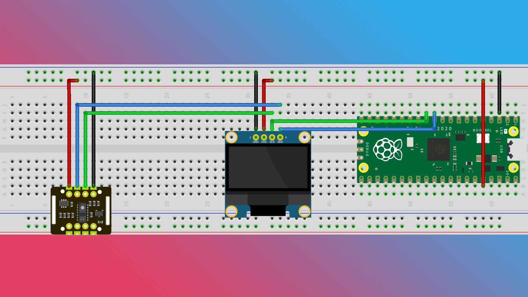
Using the breadboard to build a pulse oximeter
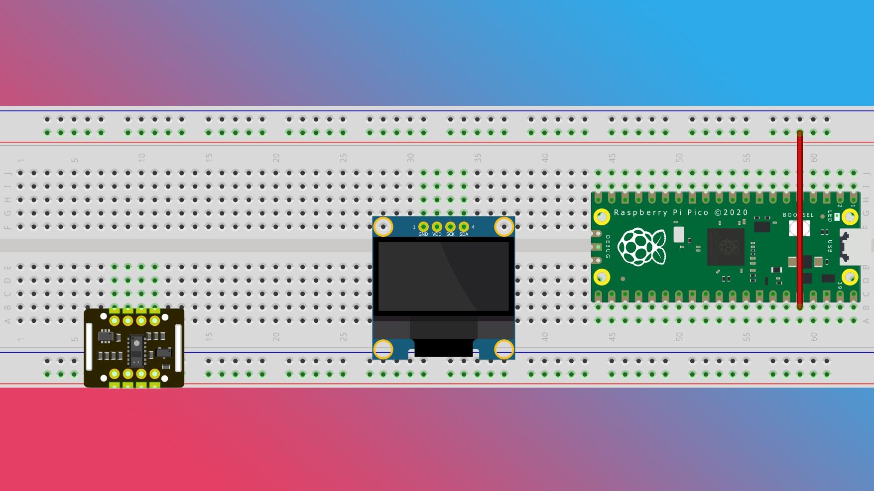
Start by placing your Raspberry Pi Pico on your breadboard, straddling the central channel with the micro USB port towards the edge. You want the port on the edge because you’re going to need easy access to it for power. Placing it in the middle of the edge maximizes the number of holes you have available to work with.

Next, place your OLED display and pulse oximeter module. It doesn’t really matter where you place them, but some spots are better than others. The OLED is best on the lowest row of the upper half of the board, so it receives support and still leaves four rows of holes, so your jump wires don’t get cramped. The pulse oximeter module is better towards the bottom of the board because it’s easier to get good contact with your finger.

Now that all of your components are in place, it’s time to wire them up. This can be done in any order, but I like to start with power.
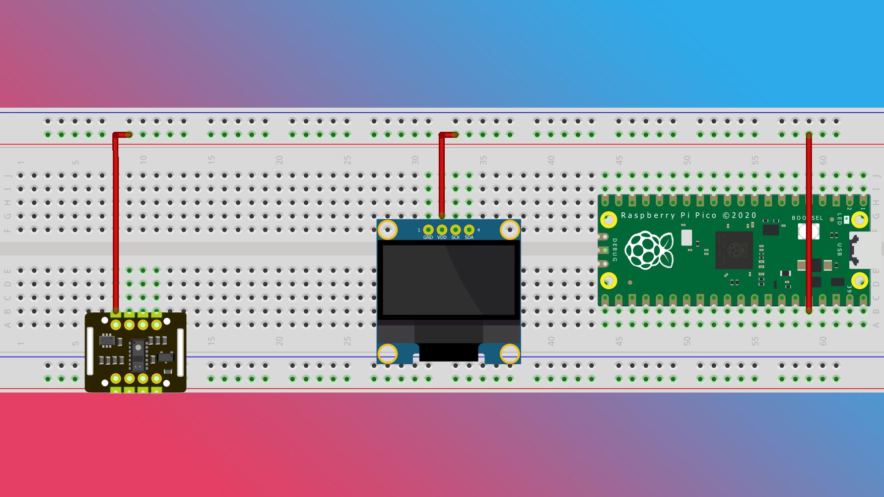
- Run a jump wire from the Pico’s 3.3V pin to one of the positive power rails on the edge of the breadboard.
Source: Fritzing - Connect the power pins on your components to the power rail.
Source: Fritzing - Run a jump wire from one of your Pico’s ground pins to a negative power rail.
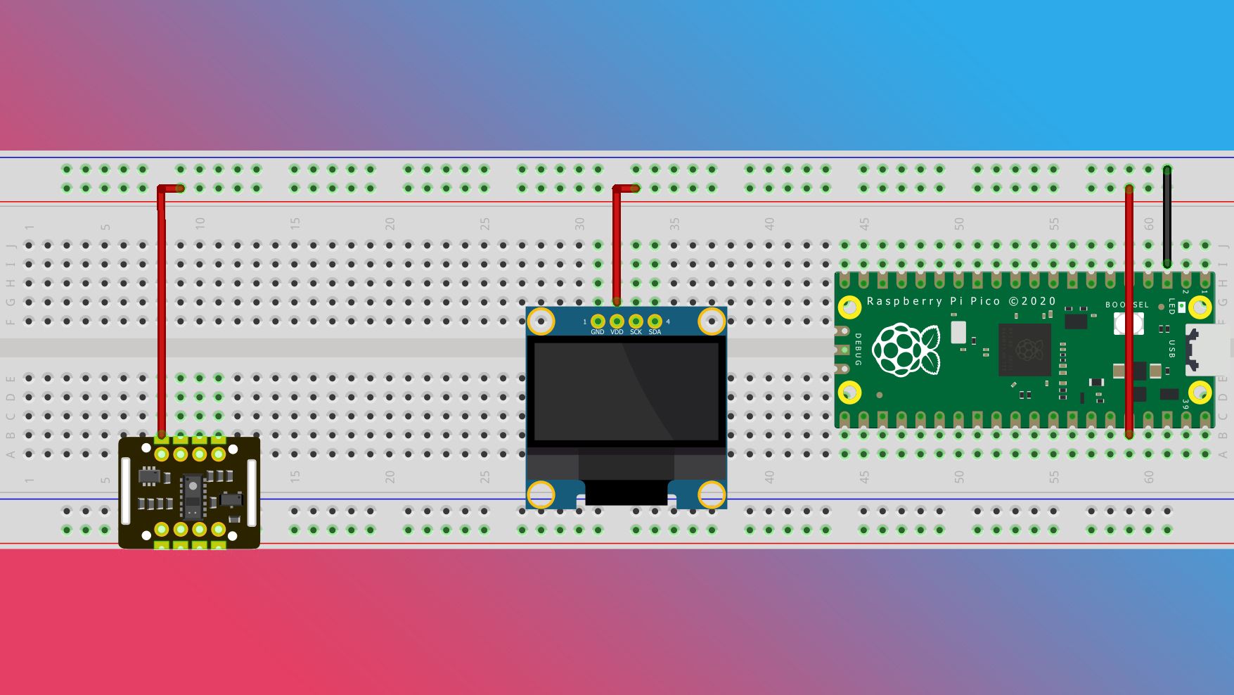
Source: Fritzing - Connect the ground pins on your components to the negative power rail.
Source: Fritzing


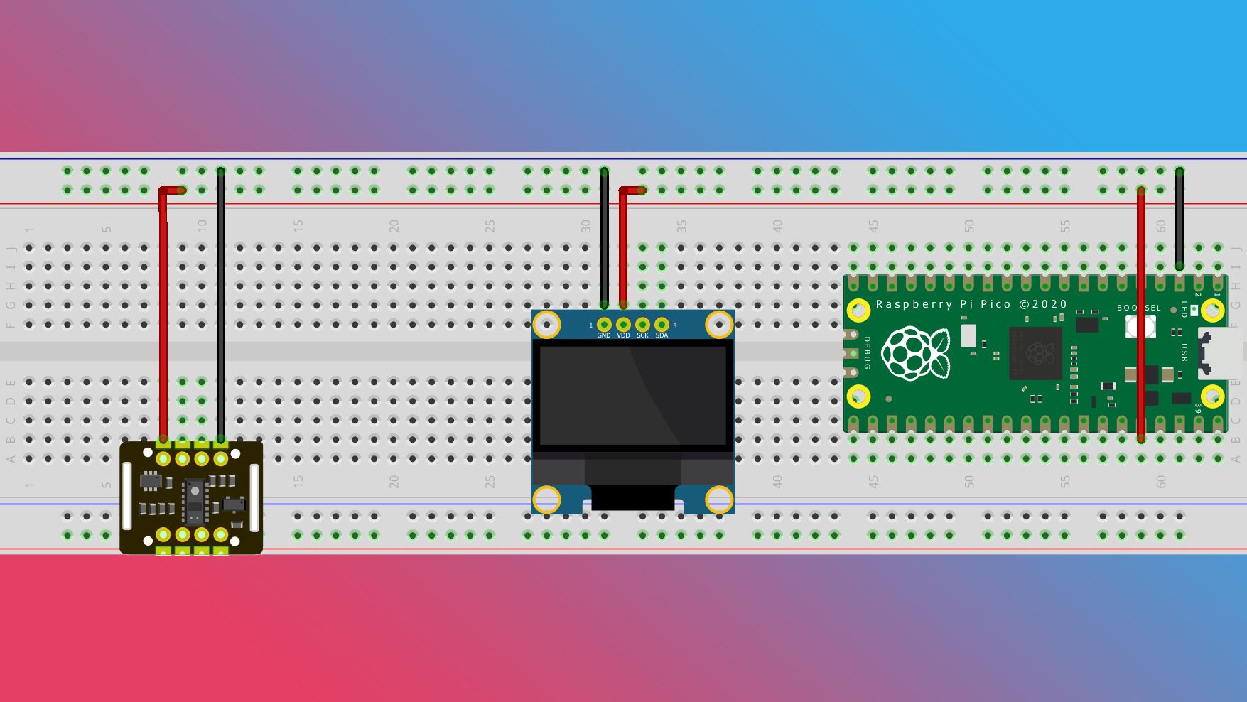
When it comes to managing the data from these sensors, we’re going to use the I²C protocol which will let multiple devices communicate over the same GPIO pins, simplifying our wiring needs. To use the I²C functionality, you need two pins: a data pin (SDA) for incoming and outgoing information, and a clock pin (SCL) to coordinate when to speak with each device. Let’s set it up.
- Start by connecting the SDA and SCL pins on your OLED to pins 8 and 9 on the Pico.

Source: Fritzing - Connect the SDA and SCL pins on the MAX30102 to their corresponding row above the OLED.
Source: Fritzing


You could have each device connected to its own I²C pin pair, but doing it this way will simplify your life if you ever decide to turn this from a project into a device.
Depending on the quality and age of your breadboard, you may have to fiddle around with the connections (I know I did).
Putting together the software for your pulse oximeter
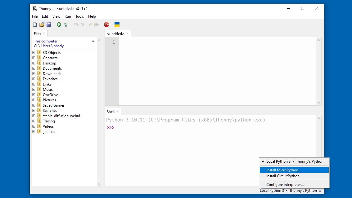
The easiest way to get the software running on your Raspberry Pi Pico is to download Thonny, an open-source Python IDE. Thonny will let you add and remove files from your Pico without a lot of fuss. Once it’s installed, you can add the Python files you will need.
Installing MicroPython to the Raspberry Pi Pico
- While holding down the BOOTSEL button, use a micro USB to USB-A cable to connect your Pico to the computer. This will make your Pico show up as a USB device and let you interact with it via Thonny.
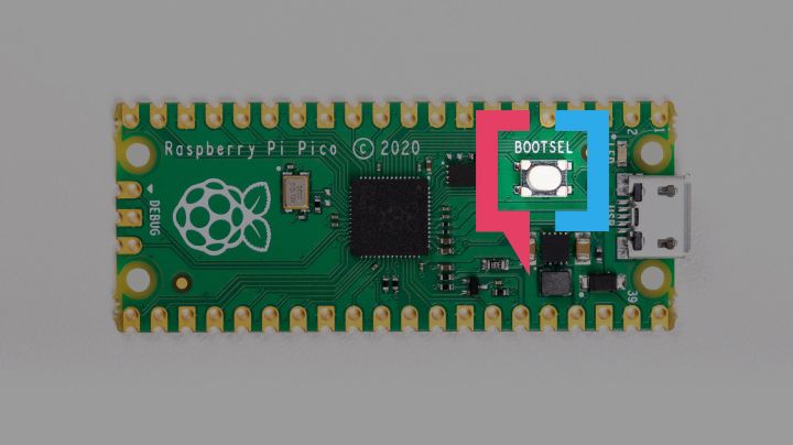
Source: Raspberry Pi - Open Thonny and look in the lower-right corner of the window. It shows you which version of Python you are currently using. Click on the text in that corner and select Install MicroPython.
- In the pop-up window, select the Raspberry Pi • Pico / Pico H option from the variant drop down, then click Install. This will install the MicroPython firmware on your Pico via the connected USB cable.
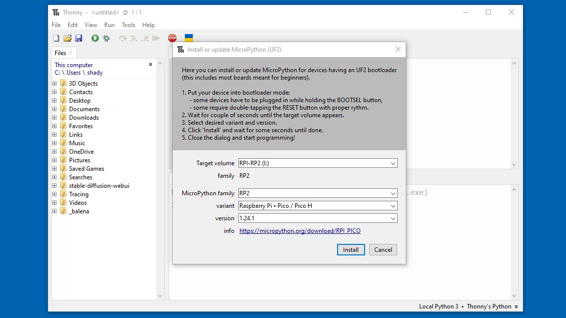
- After the installation is complete, click Close.
- Double-check the Python version in the lower-right corner. It should be set to MicroPython (Raspberry Pi Pico). If it’s not, change it.


MicroPython is a firmware that will run the Python programs that you put on the Pico. Now that we have it, let’s put some code on it.
Installing the pulse oximeter software to the Raspberry Pi Pico
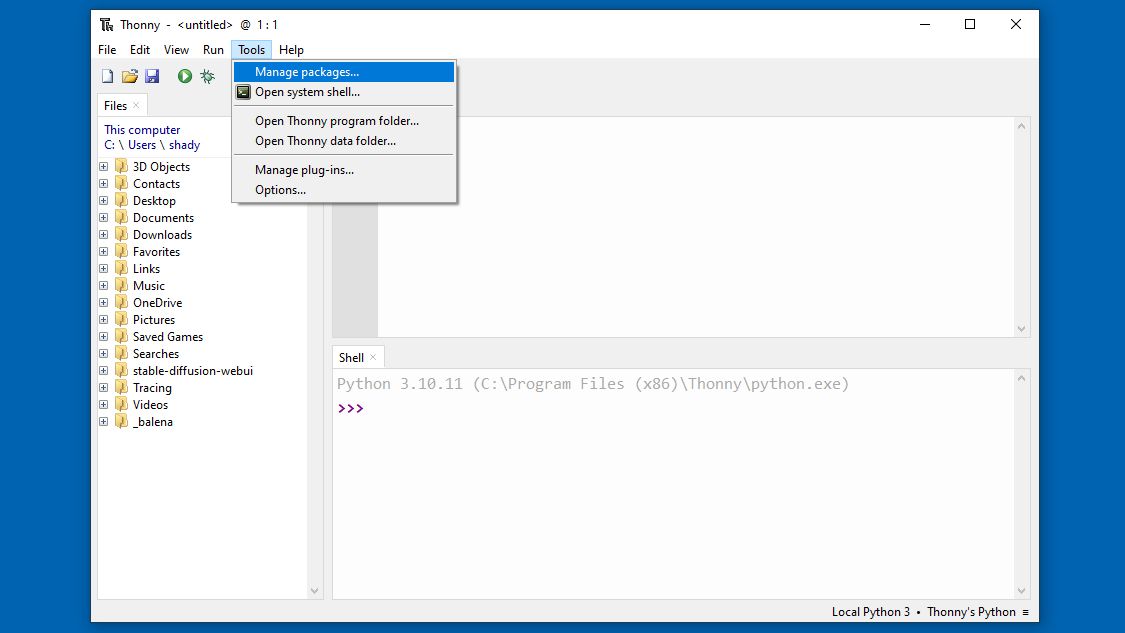
- First, you need to add the Python libraries used to interact with the display and sensor components. From the menu at the top of the Thonny window, click Tools, then select Manage Packages from the drop-down.
- The pulse oximeter code needs two libraries to function: micropython-max30102 and micropython-ssd1306. Enter micropython-max30102 into the search bar and press Enter or click Search on PyPI.
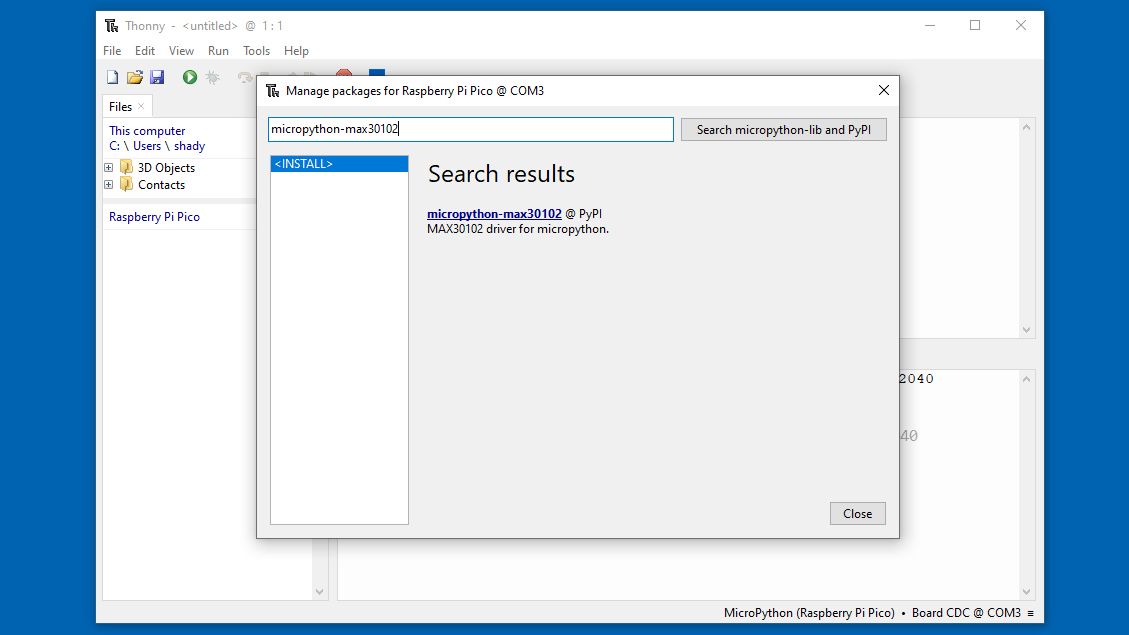
- The top result should be micropython-max30102. Click on that result, then click on Install.
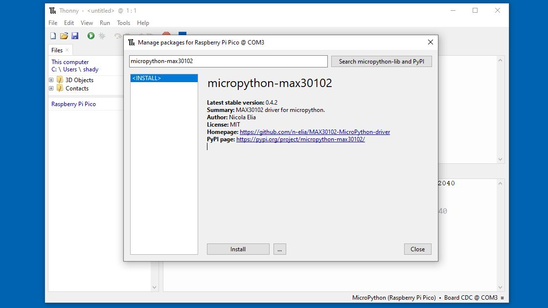
If you haven’t set your Python version to MicroPython, this installation will fail. If that happens, double-check your version in the bottom-right corner and change it if need be.
- Repeat this process to install the micropython-ssd1306 library.
- Download the pulse-oximeter.py file from GitHub.

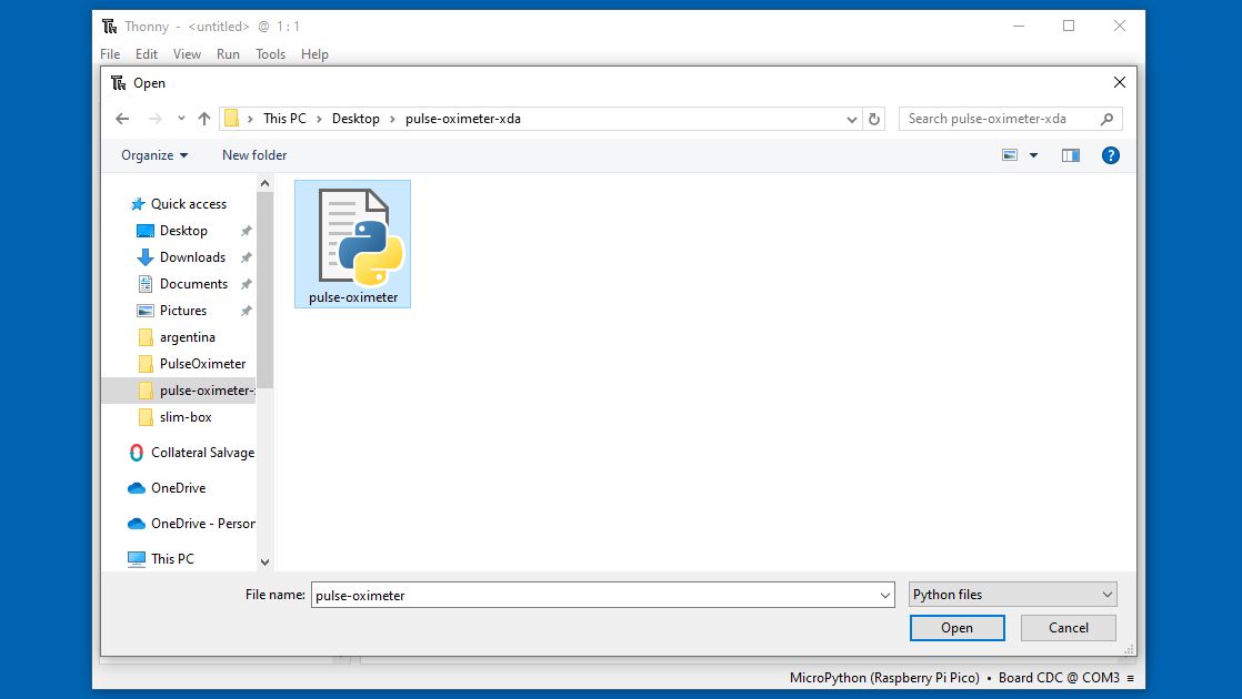
- Open the file with Thonny by selecting File from the menu, then clicking Open, then choose to open from This computer.
- Select the file you downloaded then click Open.


If all your parts are assembled, you can launch your pulse oximeter by pressing the green play button, selecting Run current script from the Run menu, or pressing F5. Finally, if you want this project to run without using Thonny, save this script as “main.py” on your Pico.

- Select File then click Save as.

- When asked where to save to, select Raspberry Pi Pico.
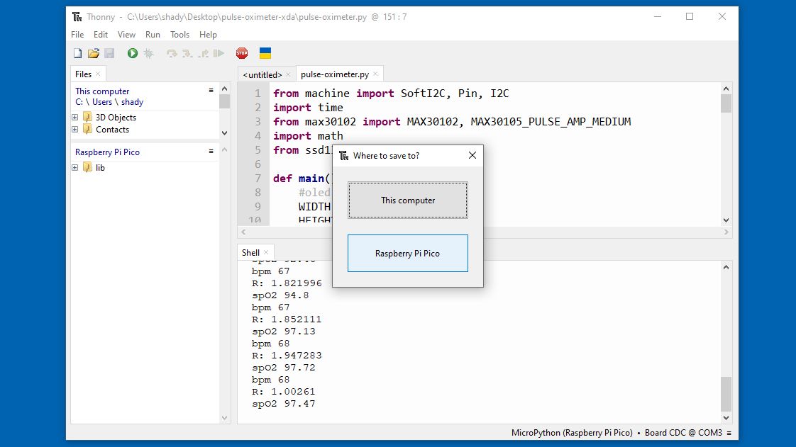
If your script is still running, you’ll have to stop it before you can save your file to the Pico.
- Name your file “main.py” and select OK.


Now, when you power your Pico, it will run your pulse oximeter script.
Make the pulse oximeter your own
Now that you have a working pulse oximeter, you can dig around in the Python code and make it your own. One easy fix is to change which pins you use on the Pico. The only restriction is the SDA signal has to go into an SDA pin and the SCL signal has to go into an SCL pin.
You also might want to tinker with the SpO² formula (you can see in the code that I tried a few formulas). Measuring blood oxygen saturation is basically an eldritch art and “proper” calibration isn’t something that can be done by yourself in your workshop. Still, don’t let propriety stop you, muck about in the code and have some fun! And at the end of the day, you’ll have valuable personal health information available at just the touch of a finger.

Related
I made an infrared trail cam with a Raspberry Pi so I can see what’s been pooping in my backyard
Harness the power of technology to spy on nature
#pulse #oximeter #Raspberry #Pico #tabs #heart #rate
source: https://www.xda-developers.com/pulse-oximeter-raspberry-pi-pico/

